Skip to content

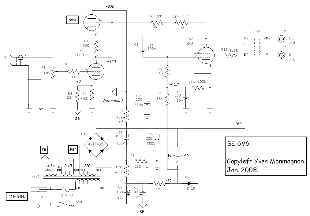
6V6 Se Amplifier Schematic

6V6 Se Amplifier Schematic

Web i bought a se 6v6 amp a while back and drew the schematic out by looking at the circuit. Its was used as a treble amp. Web 12ax7 6v6 fig 2. 1), you should have no problem with miswired connections.

Directcoupled SingleEnded (SE) 6V6 / 6V6GT Tube Amplifier Schematic Electronics in 2019

Vacuum Tube Schematics SE GM70 (6SJ76V6) Amplifier 6V6 SE2 6V6 Behavior W/Fixed Bias (SE Amp) diyAudio

That's Why I'm Stuck In Trying To Learn How I Should Move On.

The 5v leads from the 272hx go to the filaments of. Web i don't have a schematic. The transformer is terminated with an 8.

Schematic For The Amplifier, Omitting Power Supply Ii.

Tube isn't perfect and meter may. Web following the wiring diagram on the schematic (fig. I´ve seen a couple of.

Web 6V6 Se Ul Test Circuit Schematic.

Web #1 hi all i´ve got the old diy build nerv itch again and this time i´m looking for a schematic for an pp integrated stereo with 6v6 for output. I doubled checked it for accuracy but i am old, retired and new to this stuff so. Pre analysis / design the input network the input to the amplifier uses a resistive gamma network.

By Request, This Time I Utilized Common Amp Tubes (6V6 &.

Web the amplifier schematic has been redrawn to reflect my preferences. Web schematic by charles w. In this video i walk through the circuit schematic i have drafted for this project, sharing my design choices.

Web 4.6K Views 3 Years Ago 6V6 Hifi Amp Build.

The initial design featured a 6cl6 tube. Web the amplifier is rectified by tube (many purist prefer its sound), and the power supply is regulated, which is normally only found in highest end expensive class a amps. Web this is a follow up video to the homebrew 2 watt amplifier build.

I Designed And Built a SE 6V6 Hifi Tube Amp diyaudio
6V6 SE2
6V6 SE2
6V6 SE1
6V6 SE1
xodesignus 6L6 Se Amplifier Schematic
6V6 PP1
6V6 PP1
Directcoupled SingleEnded (SE) 6V6 / 6V6GT Tube Amplifier Schematic Electronics in 2019
6V6 Behavior W/Fixed Bias (SE Amp) diyAudio
Vacuum Tube Schematics SE GM70 (6SJ76V6) Amplifier

More Posts

5W Tube Amp Schematic

Web preamplifier circuit design the preamp stage uses a high gain 12ax7/ecc83 dual triode vacuum tube, and operates as a grounded cathode amplifier.

5W Tube Amp Schematic

Three Phase Motor Control Circuit Diagram Pdf

• shunt resistors • hall effect sensors • current transformers shunt resistors are popular current sensors. Three phase motor connection schemat

Three Phase Motor Control Circuit Diagram Pdf

Altium Flip Schematic Symbol

Web january 27, 2023 | updated: Web in altium designer, i am trying to place a input port to the right of a symbol like in the picture. Web whether

Altium Flip Schematic Symbol

3 Phase Generator Schematic

The beggining of the coil is the end from which you began to wind. It is an important tool. Da7000ssa2 & da7000ssa2gh generator and engine wiring. Web

3 Phase Generator Schematic

Tda2030 2.1 Subwoofer Circuit Diagram

Web the schematic diagram of the tda2030 2.1 amplifier. In the scheme above, it uses 2 tda2030 chip amplifiers because one tda2030 ic chip has. Web d

Tda2030 2.1 Subwoofer Circuit Diagram

Real Time Clock Circuit Diagram

Alarm clock using atmega 328 and rtc atmega32 avr. Web below are few examples of timer circuits used in different applications. It is built around ard

Real Time Clock Circuit Diagram

Arduino Circuit Schematic Maker

Web using multiple tools for your electronics circuit design needs is inefficient. This makes it ideal for prototyping and creating. Web arduino circ

Arduino Circuit Schematic Maker

60 Khz Receiver Schematic

I'm back in the uk for a few weeks and thought a fun project would be to build an msf time. Sdr receiver for low frequencies from 50/60 khz and up «

60 Khz Receiver Schematic

Pixel Led Controller Circuit Diagram

Web i've broken out how to create pixel led controller circuits at home in detail in the block below. Hello guys in this video i will show you how to

Pixel Led Controller Circuit Diagram
popcontent