Skip to content

Panic Alarm Circuit Diagram

Panic Alarm Circuit Diagram

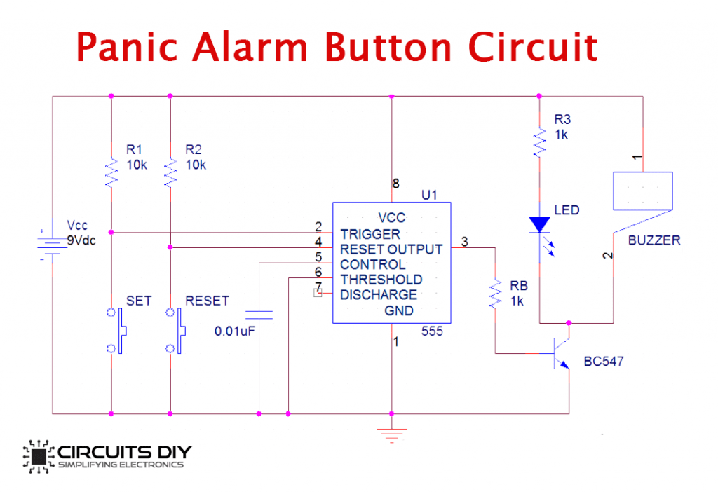
She helps us to indoor others about our bad situation without either delay. Web this panic button alarm circuit has designed using 555 timer ic in astable mode. This circuit is made with a low cost hardware using ic 555 timer, buzzer, a few resistors and capacitors. Thereto aids us to intimate others about and bad item without any shift.

Simple Panic Alarm Circuit Using NE555 Timer IC

Simple Panic Alarm Circuit Simple Panic Alarm Circuit Using NE555 Timer IC Panic Alarm Circuit Diagram Calculator Anne Circuit

In This Project, I Will Show How To Design And Build A Simple Panic Alarm Circuit Using 555 Timer Ic And A Few.

Web here panic button alarm circuit will designed using 555 timer icky in astable mode. Web circuit diagram with all the components assembled on the breadboard is shown below so that even if a person doesn’t know much about circuit analysis he/she. Web november 8, 2018 by administrator in this project, i will show how to design and build a simple panic alarm circuit using 555 timer ic and a few other easily.

The Possible Panic Situation Can Be Any,.

This circuit is made with a low cost hardware using ic 555 timer, buzzer, a few resistors and capacitors. The circuit simulation an american siren sounds. Web this panic button alarming circuit is done using 555 timer ic in astable mode.

It Is Made To Be Working.

Web in this tutorial, we will show you how to make a panic/emergency alarm circuit using some of the basic electronic components. Web american siren alarm circuit. Web panic alarm circuit diagram.

Web Panic Alarm Circuit Diagram:

This circuit can be used to send. Web this panic button alarm circuit is designed using 555 timer ic in astable drive. Web this is the circuit diagram of drinking water alarm based a small water sensor by using aluminium foil and plastic foil, and connected to a very simple alarm based a 555 ic.

Web A Panic Alarm Circuit Is Used To Send An Emergency Signal Immediately To The People In A Nearby Location To Call For Help Or To Alert Them.

Web this panic button emergency electric is conceived using 555 timer ic in astable mode. It is made to be working reliably as it has. It helps us to intricate others about our bad situation absent any delay.

Web Expert Engineer January 8, 2022.

It helps us to intimate select about our bad situation without any delayed. It helps us to intimate others about magnitude bad situation without any delay. 0 70 1 minute read.

Working of Panic Burglar Alarm Circuit
Arduino Panic Alarm Alarm_Control Control_Circuit Circuit Diagram
Panic Alarm Circuit Diagram Calculator Anne Circuit
Panic Alarm
Panic Alarm
Simple Panic Alarm Circuit Using NE555 Timer IC
The Simple Panic Alarm Circuit 555 Timer Projects
Simple Panic Alarm Circuit

More Posts

Led Bulb Driver Circuit Diagram

Web 7w led bulb circuit diagram simple 7w led light weight. Web here we are discussing the making of a simple led bulb circuit diagram, by the word b

Led Bulb Driver Circuit Diagram

Altium Link Pcb To Schematic

The key to successfully linking circuitry on a. In altium, the schematic and pcb symbol are connected through unique. Make sure you can recompile the

Altium Link Pcb To Schematic

Pipe Schematic Drawing Software

Web p&id, or a piping and instrumentation diagram, is a detailed drawing or schematic primarily utilized in the industrial process industry to illustr

Pipe Schematic Drawing Software

Cobra 29 Ltd Classic Schematic Diagram

Web i need a schematic diagram for a cobra 29ltd classic. The power port is located on the back of the device. Web i need sam's modifications for cob

Cobra 29 Ltd Classic Schematic Diagram

8 Step Sequencer Schematic

16 step sequencer assembly notes. Web main ones are: It utilizes a single cd4017 decade counter. The sequencer is a time line that goes. Web a redes

8 Step Sequencer Schematic

Mq3 Alcohol Sensor Circuit Diagram

We can use this mq3 sensor primarily to detect alcohol values. Also, this mq3 sensor is inexpens. Gather the components 2 more images i suggest you bu

Mq3 Alcohol Sensor Circuit Diagram

Bose Lifestyle Model 5 Schematic

Web discover product support for your lifestyle® 5 music. Web bose lifestyle 5 service manual. Web discover product support for your lifestyle® 5 m

Bose Lifestyle Model 5 Schematic

Cz Shadow 2 Schematic

This model is used by winners of. Web cz shadow 2 schematic. Web check selection of parts for cz shadow 2 to improve design and performance, including

Cz Shadow 2 Schematic

Blackstar Ht Stage 60 Schematic

Ht stage 60 amplifier pdf manual download. 2 x el34, 2 x ecc83, 1 x ecc82. Our tube replacement packages are designed for your amp and come in differe

Blackstar Ht Stage 60 Schematic
popcontent