Rheostat In A Circuit Diagram
Web rheostat diagrams are straightforward to recognise and understand. Similar to a potentiometer, some. This resistor has been designed to control. A key, ammeter, voltmeter, resistor,.
How a Rheostat works Step by Step & its different applications YouTube
Basics of Potentiometer Basics of Electrical Engineering Use of Rheostat Simple Circuit Variable Resistance Animation of Simple Circuit YouTube Electronic rheostat provides decades of load resistance EETimes
Web A Rheostat Circuit Diagram Is An Electrical Schematic Illustration Of A Series Of Resistors Connected In Parallel And Used To Regulate Voltage Levels In An Electronic.
Comparison chart between potentiometer and rheostat (reference:. A rheostat is a smoothly variable resistance used in order to change the flow of current in an electric circuit. The constituent parts of a rheostat are relatively easy to identify in most simple illustrations.
Web The Potentiometer In The Circuit Of Figure 3.8.6 Is Connected As A Rheostat.
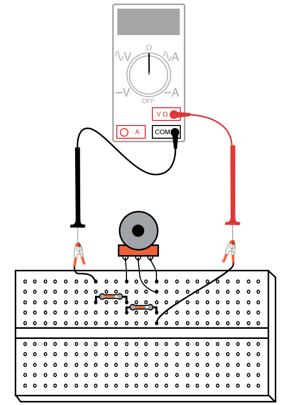
Web the above diagram shows how connections are made in a rheostat when placed in an electrical circuit. Web understand what a rheostat is used for and how a rheostat works. Web rheostat wiring diagram.
The Rheostat Is Adjusted So That The Ammeter Reading Is Always The Same For The Different Wire Length.
Rheostat wiring diagrams provide the electrical parameters for connecting a rheostat to an electrical circuit. Web you can see a comparison chart between potentiometer and rheostat at what follows: Web click here what is meant by rheostat?
One Is A Moving Point And The Other One Is A Fixed Point.
Explore a sketch of a rheostat and examples of its functionality in resistance variation. Web a rheostat is used in a circuit to change the resistance of the circuit so that the current changes. We also know that current and resistance are inversely proportional, that is.
They Are Able To Vary The.
A british scientist namely sir charles. One end of the wire from where current enters the device. To the right is a.
A Rheostat Is A Variable Resistor Which Is Used To Control Current.
Determine the maximum and minimum current in the circuit. Web home wiring diagram rheostat wiring diagram rheostat wiring diagram by wiring tech | august 2, 2022 0 comment rheostat wiring diagrams are essential. Web build the circuit as shown in the schematic and illustration, using just two terminals on the potentiometer, and see how motor speed may be controlled by adjusting.
Web A Rheostat Is A Wire Wound Variable Resistor Which Has Two Connection Points:
In this activity, students are expected to drawthe diagram of a given open circuit comprising a few circuitcomponents e.g. Web the first step in understanding a rheostat wiring diagram is to identify the primary electrical source. The resistance,r is replace with different length of the conductor thorough the experiment.
Web The Circuit Diagram Is Something Like This:
My question is why the rheostat is needed in this experiment to adjusted the current. This is typically represented as a large circle, and will be.