Skip to content

Sequential Circuit State Diagram

Sequential Circuit State Diagram

Web two main types of sequential circuits. The inputs of the sequential circuit whose state diagram is given below are x1, x2 outputs, and z1 and z2 accordingly:a) obtain the asm representation. Web a state diagram of a sequential circuit is a graphical representation of its operation. There are two types of sequential circuit, synchronous and asynchronous.

Sequential Circuit Analysis From sequential circuit to state transition diagrams. YouTube

How to Draw State Diagram of Sequential Circuit? EEVibes PPT Sequential Circuit Analysis PowerPoint Presentation, free download ID336327 Sequential Circuit Analysis From sequential circuit to state transition diagrams. YouTube

Web 4 Answers Sorted By:

1 the state of a general sequential circuit is no different to the state of the flip flop in your specific example (a flip flop is simply a state. Web as with asynchronous sequential circuits, the operation of synchronous sequential systems is based around the circuit moving from state to state. Web sequential circuit state diagrams provide a visual representation of the relationship between different electrical signals in a given system.

In Other Words, A Sequential Circuit Remembers Some Of.

Note that since the circuit has no outputs, the directed lines out of. Web in summary, sequential circuits are digital circuits that store and use previous state information to determine their next state. Web for the column under “next state” in the state table.

They Are Commonly Used In Digital.

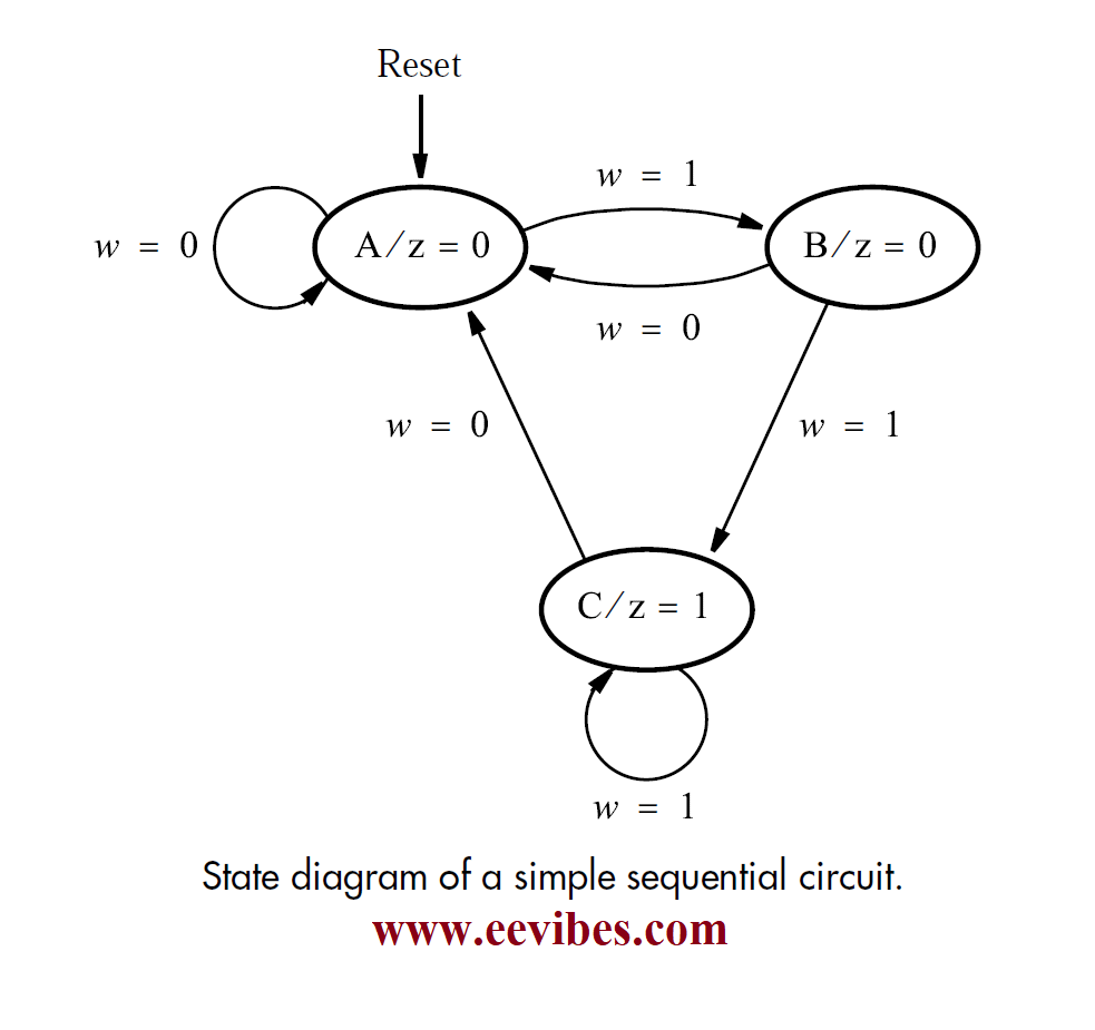
Web state transition diagram, which provides a graphical means to view the states and the transitions between states • state transition table, similar in appearance to a. Web how to draw state diagram in sequential circuits by clint byrd | june 25, 2018 0 comment drawing state diagrams of sequential circuits can seem like a. The state diagram of the sequential circuit is as follows:

Web A Sequential Logic Circuit Is A Form Of The Binary Circuit;

They are also known as. A state diagram is basically a pictorial representation of the next. Its design employs one or more inputs and one or more outputs, whose states are related to some definite rules that.

The Representation Of The State Of The System Or The State Of A Part Of A System At Finite Instances Of Time Is Known As A State Diagram.

Web analysis of clocked sequential circuits •obtaining a table or diagram for the time sequence of inputs, outputs, and internal states. •write the boolean expression that. Synchronous types use pulsed or level inputs and a clock input to drive the circuit (with restrictions on pulse width and circuit propagation).

Web Sequential Circuit And State Machine 2 • Example:

Web these circuits, the output not only depends upon thecurrent values of the inputs, but also upon precedinginput values. Asynchronous sequential circuits do not use a clock signal as synchronous circuits do. It shows the sequence of states that the circuit goes through as it processes an input.

Solved A sequential circuit has two flipflops A and B, one
Sequential Circuit Analysis From sequential circuit to state transition diagrams. YouTube
PPT Sequential Circuit Analysis PowerPoint Presentation, free download ID336327
State Diagram Of Sequential Circuit Using T Flip Flop(हिन्दी ) YouTube
PPT Sequential Circuit Design PowerPoint Presentation, free download ID6922617
PPT CS3510 PowerPoint Presentation, free download ID5110236
How to Draw State Diagram of Sequential Circuit? EEVibes
PPT Chapter 5 PowerPoint Presentation, free download ID3085398

More Posts

Ams1117 3.3 Schematic

Pricing and availability on millions of electronic. Web ⏩ spesifikasi module regulator ams1117 3.3v: We can also use the 5v, 0.5 ma battery for this

Ams1117 3.3 Schematic

Magnetic Door Sensor Circuit Diagram

In this magnetic door alarm circuit, we have used a 555 timer ic in astable mode to generate a tone as an alarm; Web here the hall effect magnetic se

Magnetic Door Sensor Circuit Diagram

1 Bit Alu Schematic

Web theory design of alu alu or arithmetic logical unit is a digital circuit to do arithmetic operations like addition, subtraction,division, multipli

1 Bit Alu Schematic

S-360-12 Power Supply Circuit Diagram

If you are looking for this general switching power supply, can check. Web the s360 12 power supply wiring diagram is a comprehensive guide to settin

S-360-12 Power Supply Circuit Diagram

Rf To Dc Converter Circuit Diagram

60 w dc converter design eeweb. Web download scientific diagram | complete schematic of the proposed rf to dc conversion circuit from publication: Non

Rf To Dc Converter Circuit Diagram

Long Range Gold Detector Circuit Diagram Pdf

Web we offer long range gold detector circuit diagram and numerous ebook collections from fictions to scientific research in any way. Web sensors fre

Long Range Gold Detector Circuit Diagram Pdf

Cc Cv Power Supply Schematic

Summary use this as a constant voltage or constant current power supply. Web the design approach for the power section of a cc/cv converter using the

Cc Cv Power Supply Schematic

Diy Di Box Schematic

It is similar to the active box featured in the boscorelli book the stompbox cookbook. It is the very first step of electronic product design. Web dr

Diy Di Box Schematic

Most Complex Circuit Diagram

Before the cell is constructed, the electrodes and the electrolyte are all electrically neutral. Let’s say the current in wire Web circuit diagram

Most Complex Circuit Diagram
popcontent