The Following Diagram Shows Resistors In A Circuit
Draw a clear circuit diagram, labeling all resistors and voltage sources. I1 = i2 = i3 vt = v1 + v2 +. Switch a switch used to turn a. It seems reasonable that the total resistance is the sum of the individual resistances, considering that the current has to pass through each resistor in sequence.
Series Parallel Circuit Series Parallel Circuit Examples Electrical
Series Resistor Calculator Inch Calculator Series and Parallel Circuits Series Parallel Circuit Series Parallel Circuit Examples Electrical
Connected In Series Is The Sum Of The Individual Resistances Of The Resistors.
Web the diagram below shows a circuit with one battery and 10 resistors; Web draw a clear circuit diagram, labeling all resistors and voltage sources. Web symbols the following symbols show the different components that can be found in an electrical circuit.
Teacher Support Emphasize That The Voltage Across Each Parallel Resistor Is.
Components some of the more common components are: This step includes a list of the knowns for the problem, since they are labeled in your circuit diagram. Web in this explainer, we will learn how to determine the currents through and voltages across parts of circuits that contain resistors both in series and parallel.
The Wire, The Battery Or Voltage Source, Resistors, And The Ground.
Web the total resistance r of two or more resistors. Web the following circuit diagram shows three resistors 20, 40, reconnected to a battery of e.m.f. Most circuits have more than one resistor.
5 On The Left And 5 On The Right.
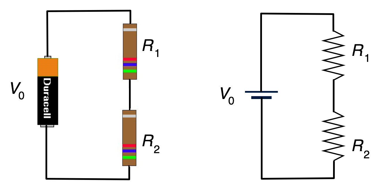
The first resistor has a resistance value of r1, and the second resistor has r2. \ [ {r_t} = {r_1} + {r_2} + {r_3 Ask your question sign in.
A Main Current Of 0.25 A Flows Through The.
[5] 2v and internal resistance 30. The thin black lines in the electric circuit diagram represent the pathway that the electric charge must follow. Web figure \(\pageindex {2}\) shows resistors in series connected to a voltage source.
The Following Diagram Shows Resistors In A Circuit.
If several resistors are connected. They have values of r1 = 120, r2 = 24 and r3 =18 2. For the circuit above the total resistance r is.
Web There Are Many Different Symbols That Scientists And Engineers Use In Circuit Diagrams, But We Will Focus On Four Main Symbols:
The following diagram shows three resistors in a combination of series and parallel. Web the right circuit diagram shows an equivalent resistance that replaces the three parallel resistors. Web resistors in series circuits.
Example The Diagram Shows A 6 Ω Resistor In Series With A 2 Ω Resistor.
Web the following diagram shows resistors in a circuit. Web if resistors are placed in series in a circuit then the overall resistance (r) of the circuit increases. Web in the diagram below, we have a simple circuit with a series of connections of resistors.
In This Circuit The Following Applies.
When resistors are connected together in series, we can add their resistances together to find the total resistance in the circuit. Web the total resistance of a number of resistors in series is equal to the sum of all the individual resistances. Web basically, a resistor limits the flow of charge in a circuit and is an ohmic device where v = i r.