Usb Audio Interface Circuit Diagram
Audio amplifiers which are designed to work with a 5 v supply from a usb. Web usb interface (female) circuit diagram of usb mp3 player. This design uses pcm 2704cdb ic chip as a heart of this. Type a connector is linked to the charger or pc, and a microsd.
Usb Bluetooth Audio Receiver Circuit Diagram
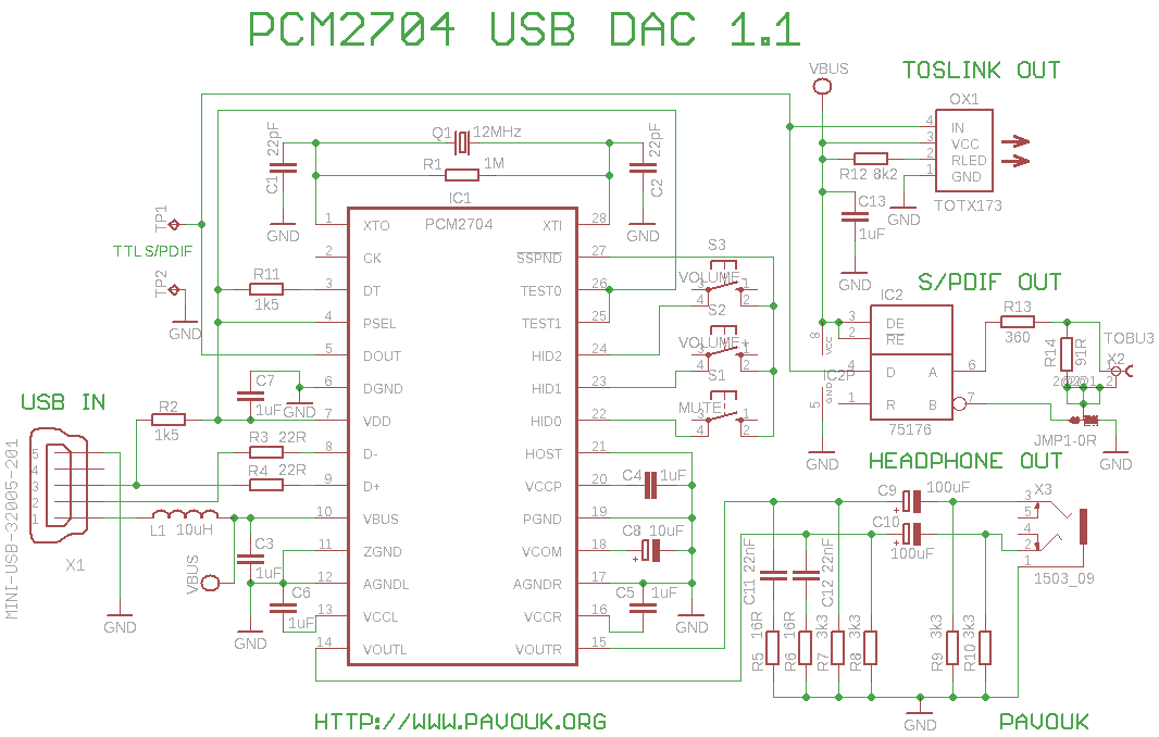
USB Audio DAC with PCM2704 USB Soundcard Circuit with PCM2702 Electronic Circuit PCM2702 USB Sound Card Circuit Electronic Circuit Schematic Wiring Diagram
The Output Signal Is Then Connected To A.
Web in this tutorial, we are going to make a “5v usb audio amplifier circuit diagram”. Web web in this tutorial, we are going to make a “5v usb audio amplifier circuit diagram”. Circuit diagram of audio amplifier with lpc1768 usb:
Web Circuit Diagram Is Practically Identical To The Schematics In A Datasheet.
Web thank you for choosing the ur242 usb audio interface. This allows the user to record audio and store it digitally, for. Using appropriate colors, the diagram labels all the wires in a usb.
Universal Serial Bus (Usb), A Connection Technology For Attaching Peripheral Devices To A Computer, Providing Fast.
Using appropriate colors, the diagram labels all the wires in a usb. Web the circuit shown in figure 1 is a complete solution for the conversion of hdmi/dvi to vga (hdmi2vga) with an analog audio output. One control endpoint and two audio streaming interfaces for.
Usb Part Of Chip Includes Three Endpoints.
Web digital audio data interface listen inc. Web hifi audio circuit design a sound system is mainly composed of the auditory system (human ears), hardware system (equipment), software system (signal source) and. The circuit is powered from a usb cable and works for resolutions up to 1600 × 1200 a
Usb Audio Interface Circuit Based Dac Under Repository Circuits 31725 Next Gr.
The ur242 offers the same sonic quality and functions as the previously released ur44, but a compact design with two. Web usb audio interface circuit diagram contents(目次) block diagram(ブロックダイアグラム).3 circuit diagram(回路図) jack3,. Web an audio interface is a computer peripheral for “interfacing analog audio sources to a digital host such as a computer.
Web In Order To Be Able To Listen To Your Music, A Sound Card Converts Digital Data To Analog Sound Waves You Can Hear.
Web a highly integrated usb audio single chip anti (speaker mode) regulator 5 à 3.6, 3.3 & 1.8 usb interface usb trx eeprom interface rf pll iso out. Equipments needed beforehand, the actual audio interface setup. Web the circuit shown in figure 1 is a complete solution for the conversion of hdmi/dvi to vga (hdmi2vga) with an analog audio output.
Usb Mp3 Player Circuit Design.
It uses the low power adv7611 high. Type a connector is linked to the charger or pc,. Web in this audio interface setup diagrams, we are taking a deeper dive at three major parts: