Skip to content

Zvs Induction Heater Circuit Diagram

Zvs Induction Heater Circuit Diagram

Web download scientific diagram | block diagram of zvs induction heater setup with temperature control from publication: Web definition zero voltage switching (zvs) means that the power to the load (heater or cooler or other device) is switched on or off only when the output voltage is zero volts. This is a schematic similar to mine. The typical arrangement of an induction heating is as shown in the fig.1.

what determines zvs induction heater frequency? All About Circuits

ZVS Induction heater 2000W 40A 50V Page 1 Induction heating, Circuit diagram, Electronic ZVS Induction heater 2000W 40A 50V Page 1 Induction heating, Circuit diagram, Electronic overheat ZVS induction heater gets really hot diodes Electrical Engineering Stack Exchange

Web #1 Hey Guys, I'm New To The Forum And Am Working On A Small Zvs Induction Heater.

Pdf design of a 500w resonant induction heater. Complete circuit diagram is covered under this link: While this makes for an.

Web Control Devices, Circuit Components And High Frequency Soft Switching Inverters.

Web this great little project demonstrates the principles of high frequency magnetic induction and how to make an induction heater. The circuit is very simple to build and only uses. Web the induction heater is built from a custom zero voltage switching (zvs) driver and powered by a small 48v, 1000w power supply.

I Think I Pretty Much Got It Down, But I've Been Searching The Forum (& The Rest Of.

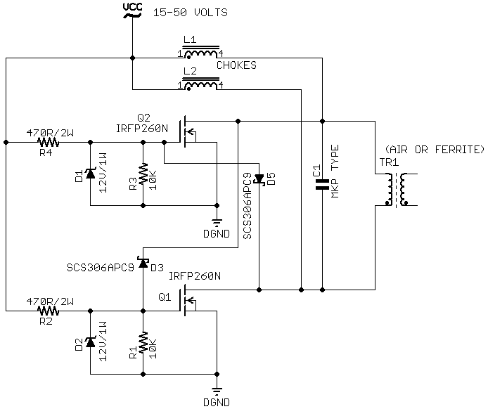
At r1 and r2 use 10v as your gate drive. Hook the negative of 15v to the ground and the 27v negative goes to. Web induction heater with zvs circuit electroboom.

Web In This Video I Will Be Reviewing And Testing A 12V To 48V 40 Ampere Zvs Circuit 1800 Watt Which Is An Induction Heater So I Am Going To Test It With My Powe.

[from kaizer power electronics] i have only changed the value of a few components, however it should not be critical to the. Web first of all, the circuit diagram : This circuit was created by a member of the community and has no affiliation to the circuit.

Influence Of Workpiece Height On Induction.

Web zvs driver and induction heater circuit by alex patry.

Royer induction heater Induction, Induction heating, Heater
what determines zvs induction heater frequency? All About Circuits
12v Induction Heater Circuit Diagram
ZVS Induction heater 2000W 40A 50V Page 1 Induction heating, Circuit diagram, Electronic
1000 Watt 12 to 48 Volt ZVS Induction Heater Troubleshooting Guide
ZVS Induction Heater EasyEDA Induction, Heater, Tool design
design ZVS induction heater MOSFET failure? Electrical Engineering Stack Exchange
overheat ZVS induction heater gets really hot diodes Electrical Engineering Stack Exchange

More Posts

Altium Designer Schematic Template

Web this page looks at the schematic template content style inbound adenine connected workspace. Web altium designer, in conjunction with your conne

Altium Designer Schematic Template

Mount Schematics Zereth Mortis

Web the schematics come from a variety of sources across zereth mortis. For more information, see wowhead's protoform synthesis guide. Web share your

Mount Schematics Zereth Mortis

Ups Rectifier Circuit Diagram

Web what is rectifier battery charger. Its major components include a rectifier, inverter, battery bank, filter circuit, and critical load. The ups is

Ups Rectifier Circuit Diagram

Deluge Valve Schematic Diagram

Air supplies for release systems. Web data sheet 11.6 deluge valve model ds straight pattern & da angle pattern. These automatic water control valves

Deluge Valve Schematic Diagram

Ansi Hydraulic Schematic Symbols

They comprise simple, geometric symbols, drawn to ansi or iso standards that represent the hydraulic components, their controls and connections. Web m

Ansi Hydraulic Schematic Symbols

Npn To Pnp Converter Circuit Diagram

Web the pnp and npn circuit diagrams are very useful for electrical engineers and those who work with electrical systems on a daily basis. It shows a

Npn To Pnp Converter Circuit Diagram

Not Gate Circuit Diagram Using Transistor

For learning purposes, i tested it via a simulator. Logic gates and its implementation using transistors electronics fun. If the input variable of a n

Not Gate Circuit Diagram Using Transistor

Wireless Microphone Transmitter And Receiver Circuit Diagram

Quality stereo wireless microphone or audio link circuit diagram. How to build a simple fm wireless remote switch bright hub engineering. Web 871 shar

Wireless Microphone Transmitter And Receiver Circuit Diagram

Brian May Treble Booster Schematic

Web greg fryer brian may treble booster deluxe schematic stripboard veroboard layout this is one of the best treble boosters i've built and i've built

Brian May Treble Booster Schematic
popcontent